Tech Specs
Steppers
There are five TMC2100 Stepper Motor Controllers (SMDs) on Replicape which support bipolar and hybrid varieties.
With the board oriented as in the above image, the wires for the steppers are:
1, 2, 3, 4 = OA2, OA1, OB1, OB2
Note
This pin out is different from Rev B2.
The peak current is rated at 2.5 A, with an RMS current pr phase of 1.2 A.
The Replicape is designed to operate without active cooling but the TMC2100 can get quite hot if peak current is sustained, especially with several stepper motors operating simultaneously. The SMDs have over temperature protection, so if a skipped steps occurs, it might be due to over heating. To address this, there are exposed areas directly under the stepper drivers where heat sinks can be mounted. Or consider adding active cooling to lead the air flow away from the gap between the BeagleBone and the cape.
While the TMC2100 stepper drivers are designed to be very quiet, high coil resistance prevents reaching the current limit causing the steppers to give off a high pitched sound.
If you are experiencing this, you might want to experiment with the “stealth mode” which will silence all steppers. See the microstepping configuration section for more information. Stealth mode might make the steppers somewhat less powerful, but should work for most printers.
To calculate if the current limit is reached or not, you can calculate the maximum coil resistance for a given input voltage. If the input voltage is 12V and you want to run your steppers on 1A current limit, the maximum coil resistance can be 12 ohm.
Warning
Some smaller stepper motors are known to produce a high pitch noise and get very warm even with a low current setting. They will appear to work, but they may very well burn do to the large heat being produced.
Heaters
Hot end and heat bed connections use Molex brand screw terminal connectors for easy connection and easy removal.
In addition to the ruggedness, the bed connector has double connections for redundancy if one wire were to come loose and for handling the larger power load.
All the heaters are controlled with Pulse Width Modulation (PWM) using SIRA34DP-T1-GE3 power MOSFeTs with a maximum voltage of 30V and a maximum current 40A. This is an update from the Rev B2 which used AON6758 that were only rated to 32A.
For a 12V Power Supply Unit (PSU), this means that the maximum power that can be used on the heated bed is 32 A x 12 V = 384 W. Please remember that there is a 20 A fuse preventing such a large power use on the heated bed. The 20 A fuse is installed to keep the traces on the PCB from over heating.
Thermistors
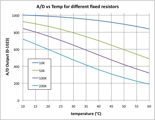
The thermistor inputs on Replicape have been designed for 100 K NTC thermistors which are most commonly used for desktop 3D-printers. 10K thermistors can also be used, however the voltage divider setup makes the 100 K thermistors more ideal since they provide more variation at typical operating temperatures.
Thermocouple
A thermocouple is not supported out of the box and requires some extra care in order to work. Most importantly is to use a voltage divider on the signal so it is converted to the 1.8V value that the analog input on the BeagleBone can handle.
Additionally, the input needs to be connected to AIN0..AIN3 (pins P9_37…P9_40).
The analog inputs used needs to be enabled by a device tree overlay, ideally by editing the current DTO.
Finally, the software needs to be hacked to make use of the new analog input and conversion.
Inductive sensors
TODO
Inductive sensors is typically mounted on the end stop marked Z2.
If you have an NPN (sinking) sensor, you can mount it directly on there.
A PNP (sourcing) type will need an added pull-down resistor externally between the signal and ground on the sensor. The value is not important, as long as it can comfortably pull a 4.7K resistor low; 1K should be fine.
DS18B20 temperature sensors
TODO
The connector marked Dallas W1 can be used for connecting temperature sensors of the type DS18B20. These are relatively low temperature sensors that can handle up to 125 degrees Celsius and are typically used for monitoring the cold end of the extruder which should never reach more than around 60 degrees when printing with PLA. The great thing about using a cold end monitor is that the temperature measurements can be used to regulate the fan on the extruder. That way, the noise level can be lowered further than when using the thermistor as a trigger for enabling the extruder fan.
Fans
Fans (or any other devices) can be PWM controlled by the four AO7400, which have a maximum voltage of 30 V and a current rating of 1.7A.
Switches as end stops
TODO
All the end stops have 4.7K (47K on Rev B3) pull-up resistors on the signal lines. Therefore, the best way to connect switches is between the signal and ground pins on the connectors. If the switches have can be connected as normally closed (NC), that is preferable since it will act as a pressed in switch if a cable has been destroyed or removed.
The signals on the end stops as as follows: | pin 1, square, signal (yellow wire in Fritzing diagram above) | pin 2, round, GND (black wire in Fritzing diagram above) | pin 3, round, VCC (red wire in Fritzing diagram above)(5V)
Power
Replicape is powered through a single 12 to 24 V power supply. This powers the BeagleBone as well, through a 5V step down converter. It also supplies 12V for fans and the inductive sensor. If the USB device connector is used, no power is drawn through the connector.
Note
If you power the BBB but not the the Replicape, the BBB will not be able
to properly communicate with it, and you will get an error such as
kamikaze redeem[675]: Error accessing 0x70: Check your I2C address or
spi.open(2, 1) IOError: [Errno 2] No such file or directory.